Disclaimer: This guideline describes the ECMO circuit for all patient populations. These guidelines describe safe practice based on extensive experience and are considered consensus guidelines. These guidelines are not intended to define standard of care and are revised at regular intervals as new information, devices, medications, and techniques become available.
The Extracorporeal Membrane Oxygenation (ECMO) circuit.
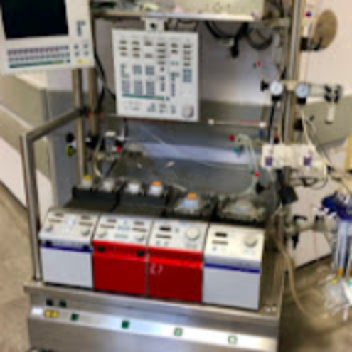
The extracorporeal membrane oxygenation (ECMO) circuit is composed of three main components including a pump, oxygenator, and heat exchanger. Venous blood is drained and then pumped through the heating component (which is usually integrated in the oxygenator), the oxygenator, and then returned to the patient. The circuit blood is returned to an artery (venoarterial ECMO [VA ECMO]) or a vein (venovenous ECMO [VV ECMO]). Circuits can have multiple access ports added as needed. The benefit of circuit access ports is the ability to administer medications, perform continuous renal replacement therapy (CRRT) through the ECMO circuit, and offer additional monitoring capabilities. However, too many connectors and access points in the circuit can lead to blood stagnation and clot formation, as well to an accidental rupture or disconnection. Highly complex ECMO systems will require a more skilled and knowledgeable ECMO specialist (the technical specialist trained to manage the ECMO system and the clinical needs of the patient on ECMO under the direction and supervision of an ECMO trained physician [ELSO Guidelines for Cardiopulmonary Extracorporeal Life Support, 2019]) available at the bedside. An ECMO specialist should have a strong intensive care background in neonatal, pediatric, or adult critical care. (ELSO Red Book 5th Edition Ch 4).
Venoarterial or Venovenous Extracorporeal Membrane Oxygenation
VA ECMO is indicated in conditions of acute cardiac failure in which the heart is unable to maintain the perfusion and metabolic demands of the body. VA ECMO is used for respiratory support in neonates and some small children, also can be used for children and adults for concomitant respiratory and cardiac failure. (ELSO Red Book 5th Edition Ch 4).
VV ECMO is traditionally used in patients with any potentially reversible condition in which the lungs are unable to ventilate and oxygenate despite the use of optimal mechanical ventilation and treatment. VV ECMO may be used in neonates due to respiratory failure. The neonate must be in a facility that has expertise in neonate respiratory failure and has double lumen cannulas available for placement. It is also available to be used as a bridge to lung transplantation, enabling patients to be weaned from mechanical ventilation and mobilize, while waiting for the transplant procedure.
Venoarterial Extracorporeal Membrane Oxygenation Cannulation Sites
Neck Cannulation
The venous cannula is inserted in the right internal jugular vein and the arterial cannula is inserted in the right common carotid artery. Using the internal jugular vein for drainage, an alternative cannulation strategy for a larger pediatric patient and/or adult patient can be used to deliver oxygenated blood using the right subclavian artery or axillary artery. Alternative cannulation technique (subclavian or axillary) can be used as it may permit increased mobility for the patient whereas reducing complications seen with groin cannulation all while preserving the carotid artery (Figure 1). (ELSO Red Book 5th Edition Ch 5).
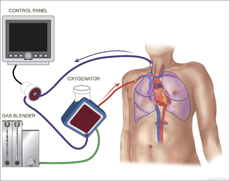
Figure 1.Venoarterial (VA) Internal Jugular Vein Subclavian Artery
Central Cannulation
Central cannulation includes direct venous cannulation into the right atrium and direct arterial cannulation of the ascending aorta. Central cannulation is most used for patients who cannot be weaned from cardiopulmonary bypass (CPB) in the operating room (OR). CPB is for short-term heart and lung support during cardiac surgical intervention. It uses a reservoir as well as an open circuit configuration for medication and volume access. ECMO is for long-term use and uses a closed configuration. Conversion between CPB and ECMO can be performed using the existing cannula. Central cannulation may be used to obtain higher bloods flows to fully support the patient’s metabolic needs during clinical conditions such as sepsis. Central cannulation enables more optimal drainage and thus better unloading of the heart than peripheral VA ECMO (Figures 2 and 3).
Figures 2.Venoarterial extracorporeal membrane oxygenation (VA ECMO) cannulation strategies.
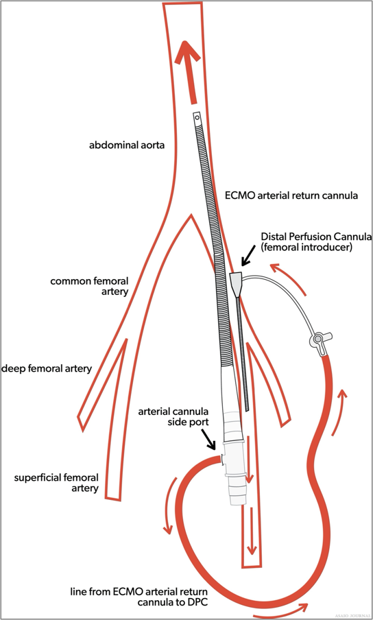
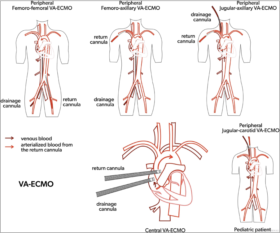
Figures 3.Venoarterial extracorporeal membrane oxygenation (VA ECMO) arterial cannula with distal perfusion cannula.
Femoral Vein and Femoral Artery Cannulation
Femoral vein and femoral artery cannulation are generally used for VA ECMO cannulation in adults and potentially children that are larger than 30kg. If the femoral artery is cannulated, a reperfusion cannula to that limb will ideally be placed to prevent limb ischemia, unless the cannulation was performed using a graft technique ensuring adequate blood flow to the lower limb. It can be beneficial during extracorporeal cardiopulmonary resuscitation (ECPR), either percutaneously or via cutdown, due to the ability to cannulate with less interference or cessation of chest compressions as in central cannulation. Due to the dual circulations (native output versus ECMO output), there will always be a degree of differential oxygenation between the upper and lower body, depending on the degree of native left ventricle and lung function. This will become more pronounced when the native lung function is poor, and the left ventricle contractility is improving. This mixing of deoxygenated blood via native cardiac output should be assessed as it can lead to myocardial and/or cerebral ischemia (ELSO Red Book 5th Edition Ch 4). It will be important to ensure the presence of a right upper extremity arterial line (right radial arterial line is preferred), cerebral oximetry, and/or pulse oximetry in the same position as the arterial line (Figure 4).
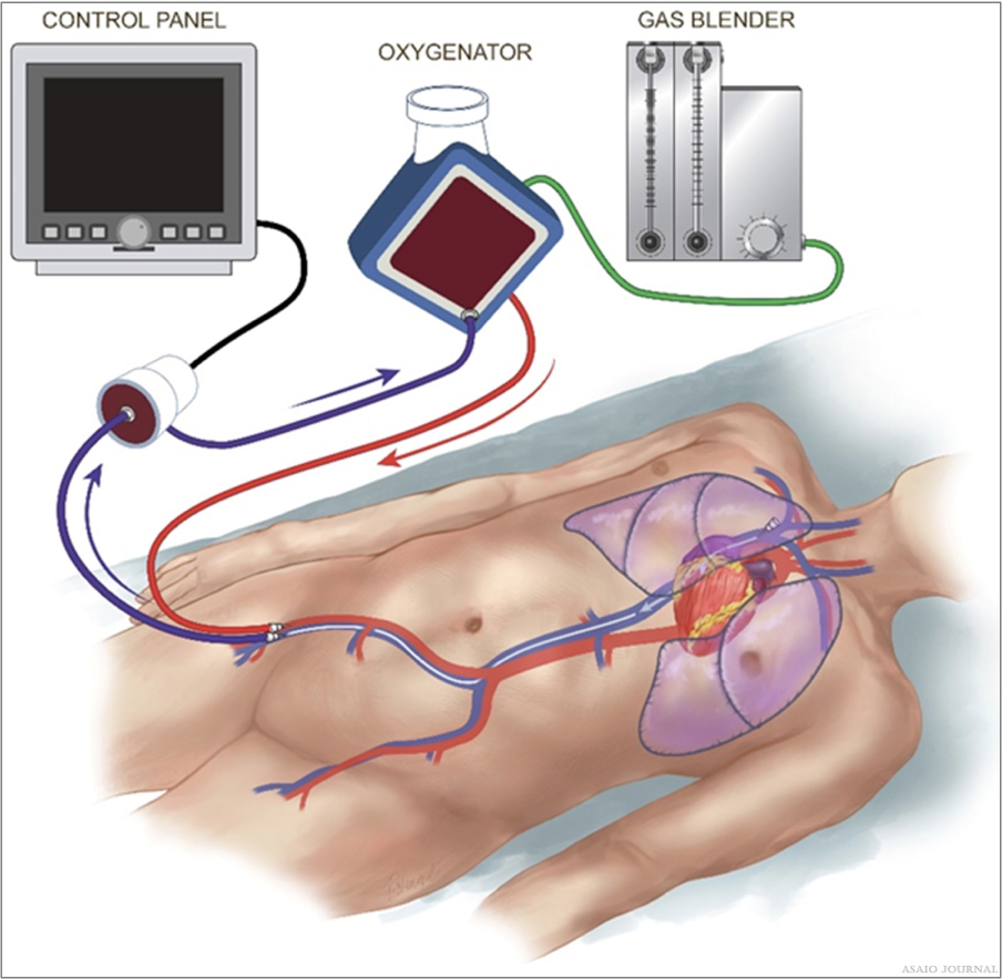
Figure 4.Venoarterial (VA) femoral vein femoral artery cannulation.
Venovenous Extracorporeal Membrane Oxygenation Cannulation Sites
Single Site Cannulation
Dual lumen cannula with the tip in the right atrium; here blood is drained via the superior vena cava (SVC) and right atrium (RA) with the oxygenated blood returned into RA towards tricuspid valve into the pulmonary artery (PA). Bicaval cannula with the tip of the cannula in the inferior vena cava (IVC); here the blood is drained via IVC/SVC and the oxygenated blood is returned via RA towards tricuspid valve into the PA. A dual lumen cannula with a single drainage site might also be positioned into the main PA; here the venous blood is drained from the RA and the oxygenated blood is directly reinfused into the PA (Figures 5 and 6).

Figures 5.. Venovenous (VV) single cannulation (RIJV).
Figures 6.Peds Venovenous (VV) single cannulation (RIJV).
Two Site Cannulation
Femoral vein/jugular vein: drainage from the femoral vein and return into the internal jugular vein or drainage from the jugular vein with blood return into the femoral vein. Femoral vein/femoral vein: drainage with a shorter cannula in the bifurcation of the femoral vein with a longer cannula returning in the right atrium or inferior vena cava. Femoral vein/pulmonary artery: drainage via a cannula posi- tioned in the RA via femoral vein and reinfusion of oxygenated blood via a second cannula positioned in the main PA through a direct or percutaneous (via the right internal jugular vein) cannulation (Figures 7 and 8).
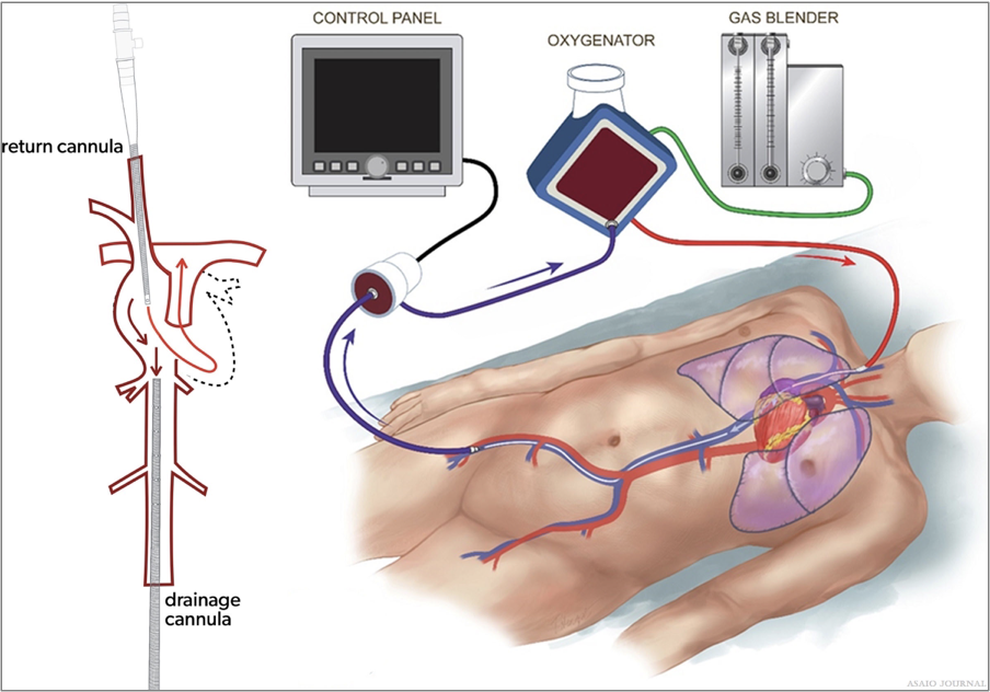
Figures 7.Venovenous (VV) femoral vein right internal jugular cannulation.
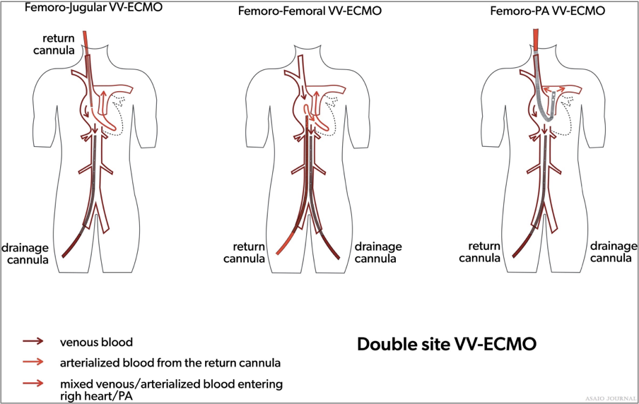
Figures 8.Two site Venovenous extracorporeal membrane oxygenation (VV ECMO) cannulation strategies.
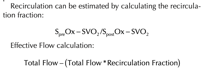
Recirculation
Recirculation occurs in VV ECMO when the reinfused oxygenated blood is drained back into the ECMO circuit causing low systemic oxygenation and high ECMO circuit inlet saturations. (ELSO Red Book 5th Edition Ch 4).
The amount of recirculation is directly related to the cannula position, pump flow, and cardiac output.
Malposition of the cannula can greatly affect the amount of recirculation i.e. Right IJ catheter is too low with two site VV or rotated the wrong way with dual lumen catheters.
It occurs when the pump blood flow rate is higher than the patient’s native cardiac output, due to left/right cardiac failure or severe pulmonary hypertension.
With adequate cardiac output and proper cannula position, pump flow increases oxygenation delivered to the patient.
Recirculation Symptoms:
Patient arterial desaturation
SVO2 and SpO2 will have a small differential between them. (Example: SVO2 87% and SPO2 92%) or in severe cases the SVO2 may be higher than the SPO2 (SVO2 92% and SPO2 87%).
The venous blood will be similarly bright red as the post oxygenator blood. If pre and post oxygenator O2 saturations are measured, both O2 saturations will be very high and only small differences will be noted (Figure 9).
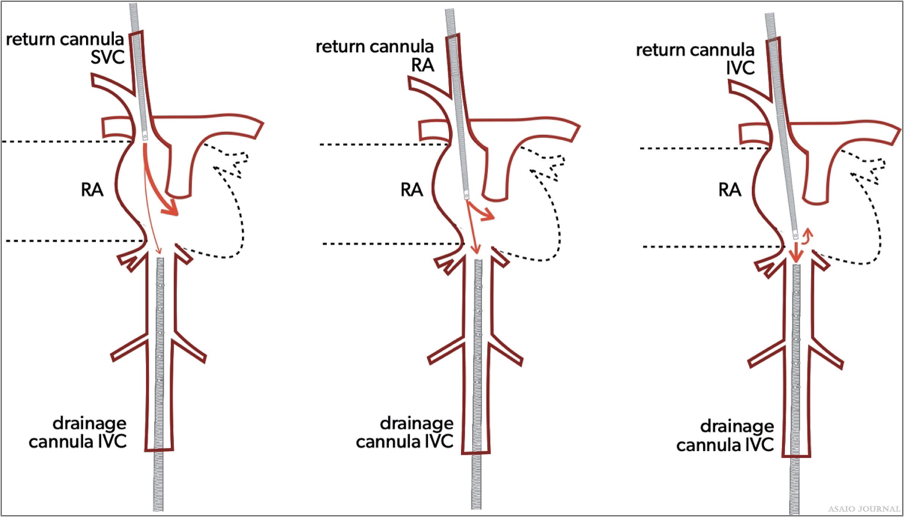
Figure 9. Recirculation.
Cannulation Selection
Selection of the right cannula is vital for a successful ECMO run and needs to be carefully selected for each individual patient. Blood flow needs to be sufficient in quantity, but also important is the efficiency in terms of where blood is drained and returned. The choice of the cannula is not only guided by the aimed degree of support, but also by the size and condition of the vessel, patient size, possible site of placement, type of insertion procedure, and desired location of blood drainage/ return. (ELSO Red Book 5th Edition Ch 4). Cannula size or diameter refers to the outer diameter of the cannula and is expressed in French (1FR = 0.33 mm). Diameter size should be selected in accordance with the desired amount of flow for the individual patient and can be guided using the pressure drop/flow charts of the available cannula (instructions for use).
Pressure Drop
Pressure drop is the difference in pressure entering the cannula and the pressure leaving the cannula. It is directly proportional to the cannula length and the viscosity of the fluid, and inversely proportional to the fourth power of cannula diameter. So, doubling the length will double the pressure drop, and doubling the size will reduce the pressure drop to 1/16th of baseline. Common practice is not to exceed a pressure drop of 100 mmHg. Hemolysis might be monitored routinely to determine nonturbulent blood flow through the cannula. Pressure drop versus flow charts are commonly used to determine the right size cannula. It should be noted that the manufacturer charts are tested using water which is an underestimation of the actual pressure drop in the blood. The Hagen–Poiseuille equation can be used to describes the relationship between pressure, resistance and flow rate (Figures 10 and 11).
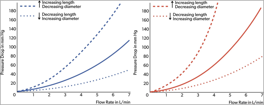
Figures 10.Arterial and venous cannula pressure drop.
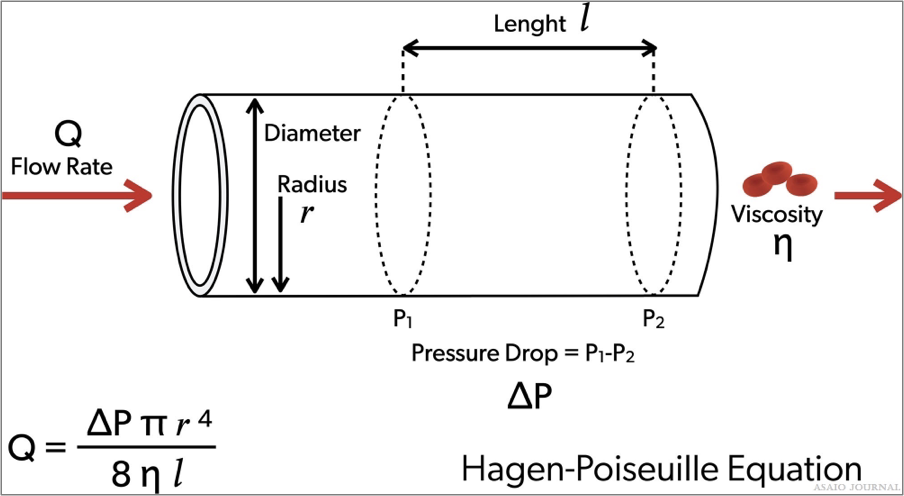
Figures 11.Hagen-Poiseuille equation.
Cannula design
Tip design and side ports
The number and position of side ports are important as it has an impact on pressure drop, the location of blood drainage, and blood reinfusion. The most common cannula designs: Blunt tip cannula: one central hole at the tip. Lighthouse tip cannula: central hole with some distal side holes around the tip. Multistage cannula: side holes at different stages along the cannula. Interrupted multistage cannula: multiple drainage ports along cannula. Number of lumen (1 or 2): dual lumen for ECMO with single insertion site (VV ECMO). Connection with tubing: with or without connector, connec- tion size (1/2”, 3/8”,1/4”, and 3/16”). Coating: to optimize biocompatibility.Wiring and stiffness: to avoid cannula kinking or collapsing. Cannula insertion tools: suited guidewires (length, stiffness, and curves) and vessel dilators (tip design, smooth transition with cannula tip) are important for uncomplicated percutaneous insertion.Cannula indicators: for placement control (Figure 12).
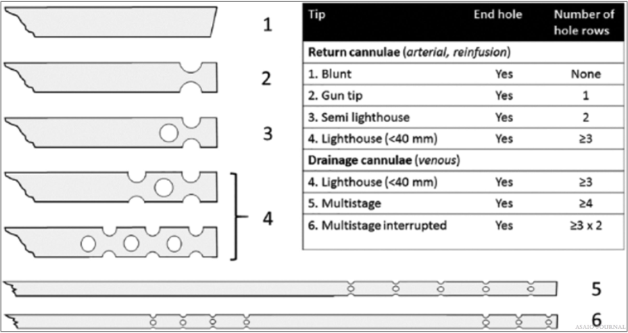
Figure 12.Different cannula tips.[2]
Overview of an extracorporeal membrane oxygenation circuit
ECMO circuits are similar for VV and VA ECMO, except that there might be extra cannulas/lines added in VA ECMO; an extra drainage line can be added if direct left ventricular unload- ing is performed via the ECMO circuit, or a return line can be added if distal perfusion of the cannulated limb is performed via ECMO. In cases of hybrid ECMO (veno-venoarterial or VP), additional drainage and return lines are hooked up to the extra cannula. These lines need to be safely incorporated in the circuit all while monitoring the additional flows. Understandably, there are different ECMO circuit sizes depending on the size of the supported patient, or the degree of required support. Size can be influenced by the choice of the oxygenator, pump, and diameter/length of the tubing (Figure 13). (ELSO Red Book 5th Edition Ch 5).
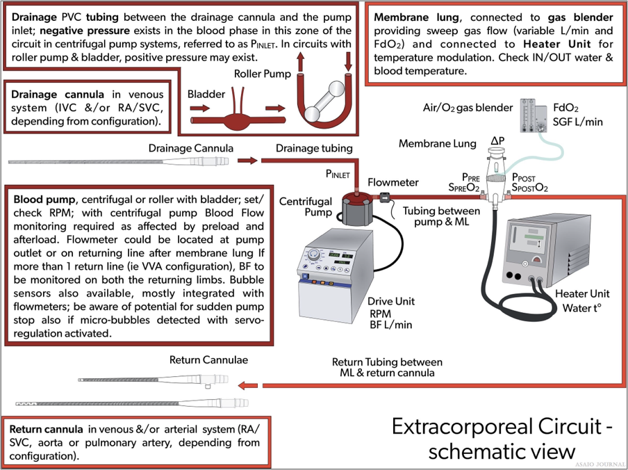
Figure 13. Overview of an extracorporeal membrane oxygenation (ECMO) circuit.
Circuit composition
The length of the tubing is center-specific. The longer the tubing, the more resistance, and the more artificial surface the patient will be exposed to. However, there needs to be enough tubing to be able to properly mobilize the patient, operate in other areas in the hospital such as the catheterization lab or the OR, and transport if needed (Figure 14).
Bridge (optional): A bridge connects the venous side of the circuit to the “arterial” side or post oxygenator using addi- tional connectors. Centers have used various types of bridges to accommodate other needs such as continuous arterial blood gas monitoring or maintaining safe flows with weaning. The bridge is used mainly for weaning neonatal and pediatric patients from VA ECMO to maintain the circuit integrity during the weaning period.
Bladder (optional): A bladder can be used to attenuate the negative venous line pressures generated by the centrifugal ECMO pump. The idea of the bladder is to act as a buffer by eliminating any trauma caused by excessive suction with the drainage catheter. The bladder is mandatory for roller pumps because it also acts as a servo-controller for the pump. The Better-Bladder allows the venous line pressure to be measured in its chamber without accessing the circuit, reducing the risk of air embolism. If no bladder is present, an additional connector with a luer-lock may be used to continuously monitor venous line (pump inlet) pressures.
Shunt (optional): If a shunt line is used, a luer connector can be added with additional tubing to direct blood flow from the positive pressure side (post oxygenator) of the circuit to the negative pressure side (pre oxygenator) of the circuit.
Benefits of Shunt: Additional monitoring such as a continuous pump arterial blood gas may be obtained through the shunt. The additional flow provided through the shunt to the oxygenator may prevent the bridge being opened when weaning flows of smaller patients. A hemofilter may be placed in the shunt for slow continuous ultrafiltration (SCUFF).
Disadvantages of Shunt: Additional connectors might induce clots and/or hemolysis, it requires additional flow monitors to assess the circuit shunt, it increases the complexity of the circuit and decreases the safety of the circuit as there is an additional risk of draining air into the negative pressure side.
Access can be obtained in the tubing from the pump head to the oxygenator by inserting connectors with luers for obtaining labs, administering medication and/or blood products.
Be aware: High pressures postpump will complicate administration of fluids and medications, and regular access may increase the risk of infection or breaking off luer locks.
Pressure transducers can be added immediately before the inlet of the oxygenator to monitor premembrane pressures and after the oxygenator to monitor postmembrane pressures. An additional transducer can be added before the pump to mea- sure drainage pressures. Pressure transducers, although not necessary, can provide information relevant to patient care while on ECMO.
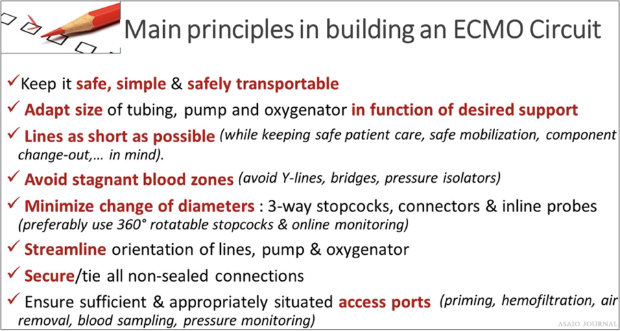
Figure 14. Main principles in composing an extracorporeal membrane oxygenation (ECMO) circuit.
Tubing
Sizes: Generally, patients less than 10–15kg have 1/4” tubing. Patients greater than 15kg typically have 3/8” tubing. (ELSO Red Book 5th Edition Ch 5) Coating: The addition of a precoating or surface modifi- cation to the ECMO circuit may be employed to reduce the adsorption of plasma proteins to the ECMO circuit and thus thrombus formation. Plasma protein adsorption to the biomaterial surface leads to platelet adhesion/activation and thrombin activation, ultimately resulting in the formation of a thrombus. Varieties of coatings exist as the perfect biocompatible surface has not yet been discovered. The addition of 25% albumin can be administered to the crystalloid primed circuit as a coating and potentially add oncotic properties (ELSO Red Book 5th Edition Ch 5). There are heparin and nonheparin surface coatings available. In case of heparin-induced thrombocytopenia, it is advisable to use a nonheparin leaching circuit.
Extracorporeal Membrane Oxygenation Oxygenator
The ECMO oxygenator is designed to administer oxygen, remove CO , and in most designs warm the blood (Figure 15). The membrane most used is made of polymethylpentene (PMP). Modern oxygenators are characterized by a low resistance to blood flow, low priming volume, easy deairing, and rare incidents of plasma leakage (ELSO Red Book 5th Edition Ch 5). Typical ranges of prime volumes range from 80mls in the smaller neonatal pediatric specific oxygenators to 250ml in the larger adult oxygenators.
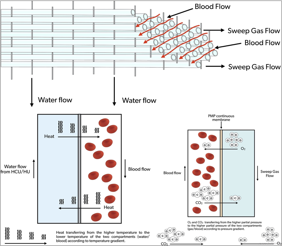
Figure 15. Extracorporeal membrane oxygenation (ECMO) oxygenator blood, gas and water flow.
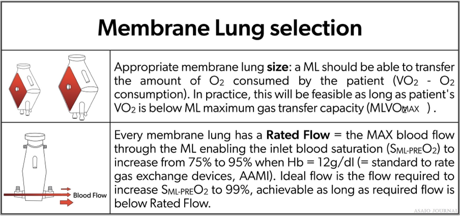
Blood Flow.
The rated blood flow must be able to transfer the amount of oxygen being consumed by the patient. (Please see table below selection of an oxygenator).
Sweep Gas
A mixture of oxygen and air administered directly to the oxygenator gas port (a blender can be used based on etiology and patient size). Increasing the sweep gas flow rate increases CO2 clearance. Decreasing the sweep gas flow rate decreases CO2 clearance.
Pressure gradient
The pressure gradient equals the difference between oxygenator inlet and outlet pressures. The pressure gradient reflects the internal resistance inside an oxygenator and its function of the specific oxygenator design in relation to the blood flow and internal buildup of deposits. Pressure drops across oxygenator membranes differ per the oxygenator manufacture. Calculating/documenting hourly pressure drops divided by flow is a common practice in some ECMO centers. If the pressure gradient rises gradually or suddenly independent of flow, resulting in an increasing quotient, this is a good indicator of oxygenator clot formation (Figures 16 and 17).
Figures 16.Selection of an extracorporeal membrane oxygenation (ECMO) oxygenator.
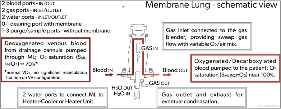
Figures 17. Membrane lung schematic view.
Complications Related to the Oxygenator
The ELSO registry defines a “failing oxygenator” as “requiring change due to clot formation, gas exchange failure, or blood leak”. Whenever an oxygenator no longer allows sufficient blood passage, gas transfer, or becomes a potential burden to the patient (in terms of inducing consumptive coagulopathy or not providing the required gas transfer), a replacement needs to be considered and an elective change-out needs to be planned as soon as possible. Postponing change-out can unnecessarily further burden the patient and might lead to an urgent change-out in suboptimal conditions, which always should be avoided. On the other hand, unnecessary change-outs also need to be avoided as these are invasive actions requiring a short support interruption, potentially causing iatrogenic infections, renewed blood dilution, additional platelet consumption as well as inflammation due to renewed surface contact activation. Additionally, ECMO oxygenator or circuits resources are burdened unnecessarily.
Increased Pressure Gradient Over an Oxygenator
Different oxygenators on the market show a different internal resistance depending on individual design and size properties, all allowing different flows at a certain driving pressure. A rise of the pressure drop is an indication of increased internal resistance, and if accompanied by a drop in flow for the same pump rotations, an indication of embolization inside the oxygenator. If not accompanied by flow reduction for the same pump rotations, there might be a pressure measurement error, which will then need to be resolved. Whenever the ECMO blood flow is relatively low in relation to the oxygenator capacity, pressure drop changes can be too subtle to serve as an early warning for clot formation. In the case of a clotted CRRT, oxygenator pressure measurements can be falsely elevated if these are measured at the site of the CRRT connection. A clotted CRRT might lead to oxygenator thrombi. Therefore, clotted CRRT devices should be removed immediately and in case of repeated clotted CRRT devices, an alternative access should be considered to connect the CRRT device.
Blood Tests
A change of trend in coagulation test results while on ECMO might indicate that clot formation is ongoing, such as rapid rising D-dimers and dropping platelet numbers. There always must be an exclusion of other potential reasons for changes in these parameters. D-dimers are very sensitive to circuit clots but can also suddenly rise due to other causes such as severe inflammation and intravascular thrombus. Most patients on ECMO show some degree of thrombocytopenia from the start of ECMO, which does not necessarily indicate solid clot formation. However, platelets can form solid clots in cases of insufficient anticoagulation or heparin-induced thrombocytopenia (HITT); here an oxygenator change-out will be required. If HITT occurs, heparin needs to be substituted by alternative anticoagulation drugs.
Gas Transfer Performance
Every oxygenator has its specific O2 transfer capacity, which can be found in the instructions for use by the manufacturer. This information gives an idea of the expected O2 transfer with a certain blood flow and gas flow of 100% FiO2. Oxygenation consumption requirements of patients can range in adults from 3 to 5ml/kg/min, pediatrics 4–6ml/kg/min, and neonatal 6–8 ml/kg/min.
Oxygen transfer during ECMO: Oxygen transferred during ECMO (V’O2) is calculated by the formula: V’O2 = BFR × (CpostO2 – CpreO2) (where V’O2 = O2 transfer across the membrane lung (ML) in ml/min, BFR = blood flow rate (L/min), C × O2 = O2 content of (pre-/post-ML) blood (ml/L). Calculating O2 content (CxO2):(CxO2): CxO2 = 13.4 × Hgb x SxO2 + 0.03 x PxO2 (Hb = hemoglobin g/dl, SxO2 = O2 saturation of pre-/post ml blood, PxO2 = PxO2 partial pressure of (pre/post-ML) blood (mm Hg) Example: (Hgb × 1.34) × (Post oxy sat – Pre oxy sat) + (PaO2 x.003) × flow (in deciliters) Patient with sp. Hct 35, SVO2 (circ) 71, SaO2 (circ) 100, Post oxygenator PO2 365 mm Hg, Pump flow 5 LPM To calculate oxygen transfer through the oxygenator: (12 × 1.34) × (1.0 – 0.71) + (365 × 0.003) × 50 = [(16.08 × 0.29) + 1.095] × 50 = (4.6632 + 1.095) × 50 = 5.7582 × 50 = 287.9 ml oxygen transfer per minute through the oxygenator CO2 transfer can be calculated as Inlet CO2 content – outlet content times blood flow, but it is more accurate to measure the amount of CO2 in the exhaust gas. CO2 transfer is always greater than O2 transfer if the membrane lung is functioning normally. CO2 transfer is controlled by adjusting the sweep gas.
Membrane lung malfunction
A calculation of O2 uptake inside the oxygenator can provide useful information with regard to the oxygenator performance. Comparing the O2-transfer by what is indicated on the instructions for use by the manufacturer might give us insight on the mL performance, but a daily trend is more important than absolute values. Before oxygenator blood is drawn for blood gas analysis, oxygenator gasses should be set at 100% FiO2 to correctly compare mL transfer capacities with the IFU. A post-oxygenator pO2 might already be indicative of sufficient O2 transfer; taken at a gas flow of FiO2 of 100%, values should exceed 300 mm Hg of PaO2. A daily blood gas control might detect deterioration of the oxygenator, and if this hap- pens accompanied by insufficient patient support, change-out needs to be considered. Similar observations can be made to detect a decline in CO2 removal. Here, the cause can simply be a wet membrane: Increasing the sweep gas for a few seconds to remove condensation or clear an obstruction that is preventing gas exchange, can improve oxygenator function. This should be performed if there is a suspicion of oxygenator failure. If mL CO2 removal rate is less than 10mm Hg despite max gas flow an oxygenator change-out should be considered. Manufacturer DNE (do not exceed) sweep gas flow rates should be noted and observed as high gas flow rates can exceed the pressure limitation set by each oxygenator resulting in membrane rupture.
Visible clots
Clots might be visible in the oxygenator depending on the design. Most clots will be situated at the venous side of the device, where internal resistance directs the blood passage through certain paths. The areas with the lowest velocity, highest resistance, or lowest wash-out will most likely clot off first. Clot growth needs to be observed and a component change should be considered if this accompanies a decreased blood flow with the same rpms, a burden to the coagulation profile of the patient (consumptive coagulopathy), hemolysis (increased PfHb), or insufficient patient support.
Oxygenator blood volume
Measurement of the transit time of a saline bolus passing through the oxygenator as recorded by a sensor placed pre and post oxygenator can enable a quantitative assessment of oxygenator performance (Figure 18).
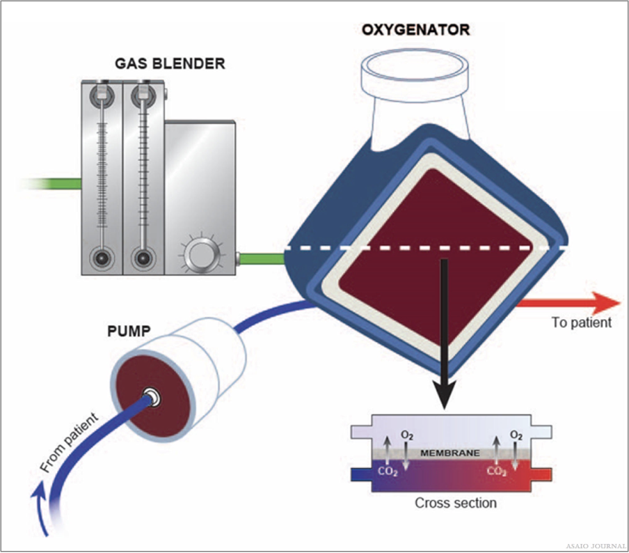
Figure 18.Illustration of blood-, gas and water path inside the oxygenator.
The ECMO Blood Pump ECMO
The blood pump controls the required blood flow for the patient. There are different designs available; roller pumps and centrifugal pumps, of which centrifugal pumps are currently the most used. (ELSO Red Book 5th Edition Ch 5).
Roller pumps
Generate direct suction on the pump inlet tubing which can be limited by a bladder (reservoir) box servo-controller to pre- vent excessive drainage catheter suction. The tubing can wear or rupture in the pump head or if there is an occlusion to the tubing after the pump (Figure 19).
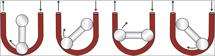
Figure 19.Roller pump example.
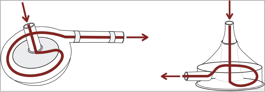
Centrifugal pumps
Magnetic driven pump rotor with axis control that gener- ates negative suction at a central hub by high rotational speed; blood is expelled via lateral hole. All centrifugal pumps have their specific control consoles which ensure pump operation, and each have certain monitoring and safety features (flow, air bubbles, pressures, visual, and auditory alarms). Most have backup batteries. There should always be a backup available (hand crank, backup motor, or spare console). If ECMO transport needs to be performed, a safely transportable system needs to be available.Performance is related to rpms and is dependent on preload and afterload (Figures 20–22).
Figures 20.Centrifugal Pump examples.
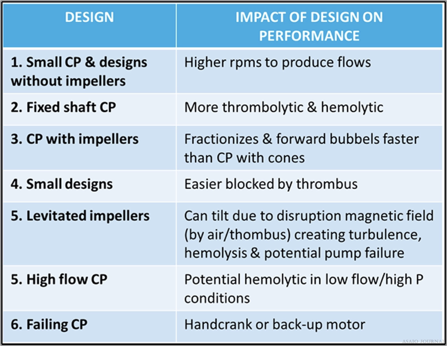
Figures 21.There are different centrifugal pump designs clinically available; all containing different features which has an impact on performance. They all behave differently towards clots and air and need different protocols with regards to troubleshooting and in case of technical failure.

Figures 22.Causes of pump failure and how to intervene.
Priming the Circuit
Circuits are primed with crystalloid solutions and/or blood products based on center preference under sterile conditions. (ELSO Red Book 5th Edition Ch 5).
Blood Prime
Infants and small pediatric patients approximately <10– 15kg should have the circuit primed with blood (packet red blood cells + hemodilution) before initiation of ECMO support, unless cardiopulmonary resuscitation is in progress, whereas the goal is to establish ECMO support as soon as possible. Blood prime additives may include NaHCO3, CaCl, Heparin, FFP, and 25% albumin. It is advisable to check the electrolyte composition of the blood prime before initiating ECMO.
Crystalloid prime
Patients >10–15kg can be primed with a crystalloid solution, but this is also dependent on the circuit to patient volume or hemodilution.
ECMO Circuit In-Line and Online Monitoring ECMO
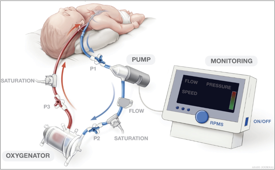
ECMO circuit monitors either connected in or placed on the circuit are intended to measure the ongoing function of the circuit and alert the operator of any undesirable conditions. Each institution should examine if pressure monitoring is appropri- ate for their ECLS patient population (Figure 23). (ELSO Red Book 5th Edition Ch 5).
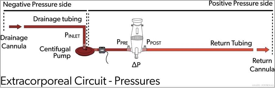
Figure 23.Extracorporeal circuit pressures.
Flow monitors
Blood flow is typically monitored directly with ultrasonic flow meters on the circuits with centrifugal pumps or calculated from tubing capacity and revolutions per minutes for roller pumps. Direct monitoring should be considered with roller pumps to ensure proper occlusion and accurate blood flow.
Circuit pressures monitoring
Inlet pressure (P1): the amount of negative pressure produced from pulling blood from the patient toward the pump. For roller pumps, servo inlet pump regulators should be utllized to ensure that gravity siphon does not result in cavitation from excessive negative pressure or air entrainment from various connectors or stopcocks. For centrifugal pumps, monitoring inlet pressure can be achieved by a circuit pressure monitoring device, which in some pumps can serve as an automatic rpm’s regulator in case of exceeding negative pressure limits (Figure 24). Pre-oxygenator pressure (P2): the pressure between the pump and oxygenator. Post-oxygenator pressure (P3): the pressure in the circuit after the oxygenator. Transmembrane pressure gradient or pressure drop (∆P) is determined by the difference between the pre-oxygenator and post-oxygenator pressure and reflects the internal resistance within an oxygenator (Figures 25–27).
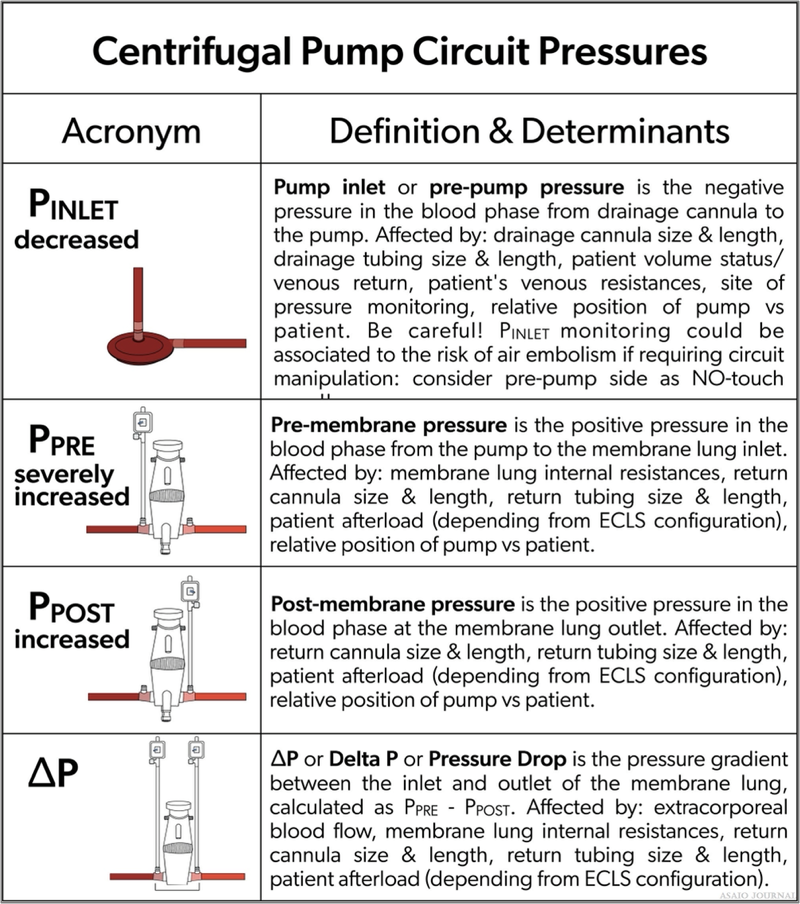
Figure 24. Centrifugal pump circuit pressures.
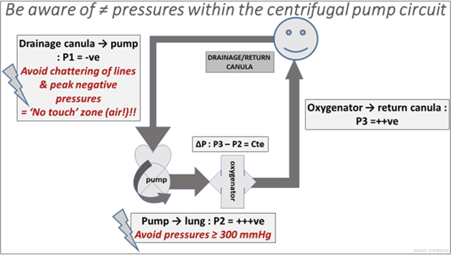
Figure 25.The 3 different pressure zones in a centrifugal pump extracorporeal membrane oxygenation (ECMO) circuit, Pressure zones in
centrifugal pump ECMO circuit are relative values and are in relation to certain variables.
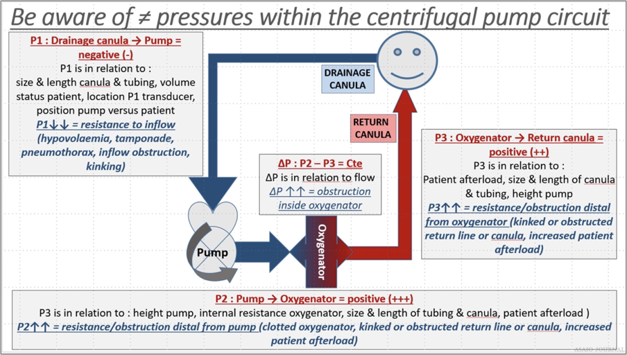
Figure 26. Pressure zones in centrifugal pump extracorporeal membrane oxygenation (ECMO) circuit are relative values and are in relation
to certain variables.
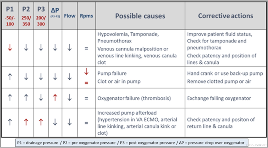
Figure 27.Relation between pressures, flow, and rpms – possible causes and corrective actions.
Peripheral arterial O2 saturation monitoring
Arterial O2 saturation (SaO2) is the fraction of oxygen-saturated hemoglobin relative to total hemoglobin in the blood.
Bubble detection
Bubbles can be detected using a noninvasive ultrasonic sensor placed on the circuit or visual recognition. A bubble detector is preferably placed postoxygenator to ensure gross air is not administered to the patient. This can be turned off during circuit maintenance to avoid confusion of air detection. The bubble detector should be in use during routine care, especially if the postoxygenator side of the circuit will be accessed routinely.
Battery indication
The console should always be plugged into an electrical out let which is designated for emergency backup electricity.
Pre-primed ECMO Circuits on Standby
Due to the time it takes to assemble and prime the ECMO circuit, many centers keep circuits assembled and filled with a crystalloid solution and will administer additives when ECMO is needed (see Priming the Circuit above). Due to the time and meticulousness that is required to not contaminate the circuit, it is best to assemble, and crystalloid primes the circuit in a con- trolled situation versus an emergent circumstance. Using the sterile technique and a solution that does not have substrates for bacterial growth, the circuit is unlikely to grow bacteria over time if contamination is prevented during standby times. Per ELSO’s Infection Control Guidelines, “it is safe to maintain prep- rimed circuits for up to 30 days, and possibly beyond 30 days, if: 1) the circuit is constructed and primed using standard sterile techniques and 2) the prime is electrolyte solution-based, and no glucose-containing solutions or albumin are used within the prime.” (ELSO Red Book 5th Edition Ch 5).
Special ECMO Configuration
An additional cannula may be configured into the circuit because of lack of drainage (adding a [venous] drainage catheter) or the need of additional oxygen delivery (adding an additional return catheter). The use of flow-controlling maneuvers (Hoffman clamp) may be needed in these configurations to deliver desired blood flows to certain areas of the patient. Additional flowmeters can be used to determine accurate flows going to each location.
When and where to clamp off the ECMO circuit?
Weaning from ECMO
Decreasing the amount of support to the patient to determine the patient’s readiness to come off ECMO support (Figure 28). When weaning, one must be cognizant of the minimum flow required through the oxygenator as recommended by the manufacturer. To achieve the minimal flow indicated by the manufacturer, the bridge can be opened (if applicable) or a shunt can be added to the circuit, which will increase the blood flow through the oxygenator while maintaining low blood flows to the patient. (ELSO Red Book 5th Edition Ch 51).
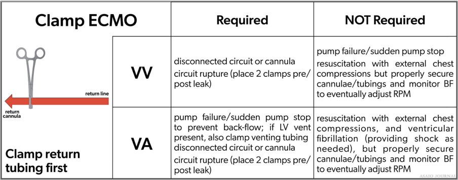
Figure 28.Where to clamp the extracorporeal membrane oxygenation (ECMO) circuit.
VA ECMO
Low flow trial
Consider additional anticoagulation or increase anticoagu- lation levels, to prevent clot formation during low flow trials with a VA ECMO wean. Wean gradually during a low flow trial according to institu- tional protocol. Do not leave blood flow under recommended low blood flow limits longer than necessary. Pump controlled retrograde flow can also be used.
Clamp trial
Consider brief clamp trials in neonatal and pediatric patients before decannulation.
VV ECMO
Turning off the sweep gas to the oxygenator: the gas line can be disconnected to ensure there is no gas exchange occurring. A VV clamp trial does not require clamping off blood flow because there is no cardiac support being provided to the patient. Capping off is usually done for a minimum of several hours to assure patient’s tolerance of decannulation.
Terminology
For nomenclature terminology for different types of ECMO, please refer to the extracorporeal life support organization maastricht treaty for nomenclature in extracorporeal life support, a position paper of the extracorporeal life support organization.
Acknowledgements
The authors thank Christine Stead, CEO, Peter Rycus, Executive Director, and the Members of the Board for their invaluable contribution to the development of this guideline
References
- Brogan TV, Lequier L, Lorusso R, MacLaren G, Peek GJ: Extracorporeal life support: The ELSO red book. (5th ed.). Ann Arbor, MI: Extracorporeal Life Support Organization. 2017.
- Broman LM, Prahl Wittberg L, Westlund CJ, et al: Pressure and flow properties of cannulae for extracorporeal membrane oxygenation II: Drainage (venous) cannulae. Perfusion 34(Suppl 1): 65–73, 2019.
- Extracorporeal Life Support Organization Registry: The ELSO Registry. Retrieved from www.ELSO.org. ELSO Data Registry Guidelines – Definitions. Accessed February 2021.
- Zachary B, Vercaemst L, Mason P, et al: How I approach mem- brane lung dysfunction. Critical Care 24:671, 2020.
- Westrope C, Harvey C, Robinson S, Speggiorin S, Faulkner G, Peek GJ: Pump controlled retrograde trial off from VA-ECMO. ASAIO J 59: 517–519, 2013.
- Conrad SA, Broman LM, Taccone FS, et al: The extracorporeal life support organization maastricht treaty for nomenclature in extracorporeal life support. A position paper of the extracorpo- real life support organization. Am J Respir Crit Care Med 198: 447–451, 2018.